Punjab State Board PSEB 12th Class Physics Important Questions Chapter 4 Moving Charges and Magnetism Important Questions and Answers.
PSEB 12th Class Physics Important Questions Chapter 4 Moving Charges and Magnetism
Very short answer type questions
Question 1.
Using the concept of force between two infinitely long parallel current carrying conductors define one ampere of current.
Answer:
One ampere is that value of current which flows through two straight, parallel infinitely long current carrying conductors placed in air or. vacuum at a distance of 1 m and they experience a force of attractive or repulsive nature of magnitude 2 × 10⁻⁷ N/m on their unit length.
Question 2.
State Ampere’s circuit law.
Answer:
It states that the line integral of the magnetic field \(\vec{B}\) around any closed circuit is equal to p0 times the total current passing through this closed circuit.
\(\oint \vec{B} \cdot \overrightarrow{d l}\) = μ0 I
![]()
Question 3.
A narrow beam of protons and deuterons, each having the same momentum, enters a region of uniform magnetic field directed perpendicular to their direction of momentum. What would be the ratio of the radii of the circular path described by them?
Answer:
For the given momentum of charge particle, radius of circular paths depends on charge and magnetic field as
r = \(\) ⇒ r ∝ \(\)
For given momentum,
∴ rproton : rdeuteron = 1 : 1
As they have same momentum and charge moving in a small magnetic field.
Question 4.
Write the expression, in a vector form, for the Lorentz magnetic force \(\overrightarrow{\boldsymbol{F}}\) due to a charge moving with velocity \(\vec{v}\) in a magnetic field \(\overrightarrow{\boldsymbol{B}}\). What is the direction of the magnetic force?
Answer:
Force, \(\vec{F}=q(\vec{v} \times \vec{B})\)
Obviously, the force on charged particle is perpendicular to both velocity \(\vec{v}\) and magnetic field \(\vec{B}\).
Question 5.
When a charged particle moving with velocity \(\vec{v}\) is subjected to magnetic field \(\overrightarrow{\boldsymbol{B}}\), the force acting on it is non-zero. Would the particle gain any energy?
Answe:
No. (i) This is because the charge particle moves on a circular path.
(ii) \(\vec{F}=q(\vec{\nu} \times \vec{B})\)
and power dissipated p = \(\vec{F} \times \vec{V}\)
= q \((\vec{v} \times \vec{B}) \times \vec{y}\) = p\((\vec{v} \times \vec{v}) \times \vec{B}\)
The particle does not gain any energy.
Question 6.
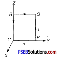
A square coil OPQR of side a carrying a current 7, is placed in the Y-Z plane as shown here. Find the magnetic moment associated with this coil.
Answer:
The magnetic moment associated with the coil, is \(\vec{\mu}\)m = Ia2î
![]()
Question 7.
Under what condition is the force acting on a charge moving through a uniform magnetic field is minimum?
Answer:
Fm = qvB sinθ; for minimum force sinθ = 0. i.e., force is minimum when charged particle move parallel or anti-parallel to the field.
Question 8.
What is the nature of magnetic field in a moving coil galvanometer?
Answer:
The nature of magnetic field in a moving coil galvanometer is radial.
Question 9.
Verify that the cyclotron frequency ω = eB/m has the correct dimensions of [T]-1. (NCERT Exemplar)
Or A charged particle of charge e and mass m is moving in an electric field E and magnetic field B. Construct dimensionless quantities and quantities of dimension [T]-1. (NCERT Exemplar)
Answer:
For a charge particle moving perpendicular to the magnetic field, the magnetic Lorentz forces provides necessary centripetal force for revolution.
\(\frac{m v^{2}}{R}\) = qvB
On simplifying the terms, we have
∴ \(\frac{q B}{m}=\frac{v}{R}\) = ω
Finding the dimensional formula of angu
∴ [ω] = \(\left[\frac{q B}{m}\right]=\left[\frac{v}{R}\right]\) = [T] -1
![]()
Question 10.
Show that a force that does no work must be a velocity dependent force. (NCERT Exemplar)
Answer:
Let no work is done by a force, so we have
dW = F.dl = 0
⇒ F. v dt = 0 (Since, dl = v dt and dt ≠ 0)
⇒ F.v = 0
Thus, F must be velocity dependent which implies that angle between F and v is 90°. If v changes (direction), then (directions) F should also change so that above condition is satisfied.
Question 11.
The magnetic force depends on v which depends on the inertial frame of reference. Does then the magnetic force differ from inertial frame to frame? Is it reasonable that the net acceleration has a different value in different frames of reference? (NCERT Exemplar|
Answer:
Yes, the magnetic force differ from inertial frame to frame. The magnetic force is frame dependent.
The net acceleration which comes into existing out of this is however, frame independent (non-relativistic physics) for inertial frames.
Question 12.
An electron enters with a velocity υ = υ0î into a cubical region (faces parallel to coordinate planes) in which there are uniform electric and magnetic fields. The orbit of the electron is found to spiral down inside the cube in plane parallel to the x-y plane. Suggest a configuration of fields E and B that can lead to it. (NCERT Exemplar)
Answer:
Considering magnetic field B = B0k̂, and an electron enters with a velocity v = v0î into a cubical region (faces parallel to coordinate planes). The force on electron, using magnetic Lorentz force, is given by
F = -e(v0î x B0k̂) = ev0B0î
which revolves the electron in x-y plane.
The electric force F = -eE0k̂ accelerates e along z-axis which in turn increases the radius of circular path and hence particle traversed on spiral path.
![]()
Short answer type questions
Question 1.
Write any two important points of similarities and differences each between Coulomb’s law for the electrostatic field and . Biot-Savart’s law for the magnetic field.
Answer:
Similarities: Both electrostatic field and magnetic field
- follows the principle of superposition.
- depends inversely on the square of distance from source to the point of interest.
Differences I
- Electrostatic field is produced by a scalar source (q) and the magnetic
field is produced by a vector source (I\(\overrightarrow{d l}\)). - Electrostatic field is along the displacement vector between source and point of interest; while magnetic field is perpendicular to the plane, containing the displacement vector and vector source.
- Electrostatic field is angle independent, while magnetic field is angle
dependent between source vector and displacement vector.
Question 2.
State the underlying principle of a cyclotron. Write briefly how this machine is used to accelerate charged particles to high energies.
Or State the principle of the working of a cyclotron. Write two uses of this machine.
Answer:
The combination of crossed electric and magnetic fields is used to increase the energy of the charged particle. Cyclotron uses the fact that the frequency of revolution of the charged particle in a magnetic field is independent of its energy.
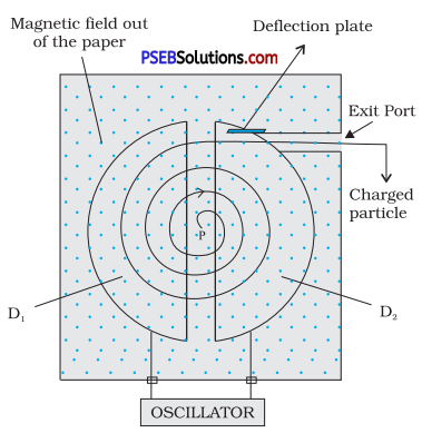
Inside the dees the particle is shielded from the electric field and magnetic field acts on the particle and makes it to go round in a circular path inside a dee.
Every time, the particle moves from one dee to the other it comes under the influence of electric field which ensures to increase the energy of the particle as the sign of the electric field changed alternately.
The increased energy increases the radius of the circular path so the accelerated particle moves in a spiral path.
Since, radius of trajectory
r = \(\frac{v m}{q B}\)
∴ v = \(\frac{r q B}{m}\)
Hence, the kinetic energy of ions
= \(\frac{1}{2}\)mv2 = \frac{1}{2}\(\)m\(\frac{r^{2} q^{2} B^{2}}{m^{2}}\)
⇒ KE = \(\frac{1}{2}\)\(\frac{r^{2} q^{2} B^{2}}{m}\)
![]()
Question 3.
(i) State Ampere’s circuital law expressing it in the integral form.
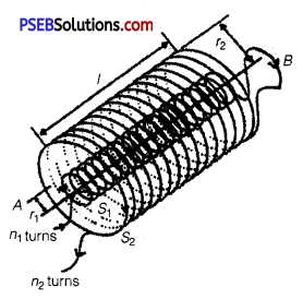
(ii) Two long co-axial insulated solenoids S1 and S2 of equal length are wound one over the other as shown in the figure. A steady current I flows through the inner solenoid S1 to the other end B which is connected to the outer solenoid S2 through which the some current I flows in the opposite direction so, as to come out at end A. If n1 and n2 are the number of turns per unit length, find the magnitude and direction of the net magnetic field at a point
(a) inside on the axis and
(b) outside the combined system.
Answer:
(i) Ampere’s circuital law states that the line integral of magnetic field
(B) around any closed path in vacuum is μ0 times the net current (I) threading the area enclosed by the curve.
Mathematically, \(\oint \vec{B} \cdot d \vec{l}\) = μ0I
Ampere’s law is applicable only for an Amperian loop as the Gauss’s law is used for Gaussian surface in electrostatics.
(ii) According to Ampere’s circuital law, the net magnetic field is given by
B = μ0nî.
(a) The net magnetic field is given by
Bnet = B2 – B1
μ0n2I2 – 0n1I1
= μ0I(n2 – n1)
The direction is from B to A.
(b) As the magnetic field due to Sx is confined solely inside S1 as the solenoids are assumed to be very long. So, there is no magnetic field outside S1 due to current in S1, similarly there is no field outside S2.
Bnet = 0
Question 4.
(a) State Biot-Savart law and express this law in the vector
form.
(b) Two identical circular coils, P and Q each of radius R, carrying currents 1 A and √3 A, respectively, are placed concentrically and perpendicular to each other lying in the XY and YZ planes. Find the magnitude and direction of the net magnetic field at the centre of the coils. ’
Answer:
(a) According to Biot-Savart’s law the magnitude of the magnetic field \(\overrightarrow{d B}\) due to a small element of length dl of a current carrying wire at a point P, is proportional to the current I, the element length dl and is inversly proportional to the square of the distance r. It is also proportional to sinθ,
where θ is the angle between \(\overrightarrow{d l}\) and \(\vec{r}\).
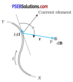
Its direction is perpendicular to the plane containing \(\overrightarrow{d l}\) and \(\vec{r}\) in vector form
\(\overrightarrow{d B}\) ∝ \(\frac{I \overrightarrow{d l} \times \vec{r}}{r^{3}}\)
⇒ \(\overrightarrow{d B}\) = \(\frac{\mu_{0}}{4 \pi} \cdot \frac{I d \vec{l} \cdot \vec{r}}{r^{3}}\)
(\(\overrightarrow{d l}\) is directed along the length of the wire in the direction of current and
\(\vec{r}\) is the vector joining the centre of current element to the point P) (b) Field due to current in coil P is
\(\vec{B}\)2 = \(\frac{\mu_{0} I_{1}}{2 R}\) .k̂
(Assuming current to be anticlockwise as seen form + ve Z-axis) and that due to current in coil Q is
\(\vec{B}\)2 = \(\frac{\mu_{0} I_{2}}{2 R} \hat{i}\)
(Assuming current to be anticlockwise as seen form positive X-axis)
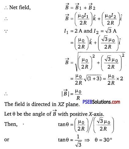
![]()
Question 5.
Explain, giving reasons, the basic difference in converting a galvanometer into (i) a voltmeter and (ii) an ammeter.
Answer:
(i) In converting a galvanometer into a voltmeter, a very high suitable resistance is connected in series to its coil. So, the galvanometer gives full scale deflection.
(ii) In converting a galvanometer into an ammeter, a very small suitable resistance is connected in parallel to its coil. The remaining pair of the current i.e., (I – Ig) flows through the resistance. Here I = Circuit current
and Ig = Current through galvanometer.
Question 6.
A current carrying loop consists of 3 identical quarter circles of radius R, lying in the positive quadrants of the x-y, y-z and z-x planes with their centres at the origin, joined together. Find the direction and magnitude of B at the origin. (NCERT Exemplar)
Answer:
For the current carrying loop quarter circles of radius R, lying in the positive quadrants of the x-y plane
B1 = \(\frac{\mu_{0}}{4 \pi} \frac{I(\pi / 2)}{R}\) = k̂\(\frac{\mu_{0}}{4} \frac{I}{2 R}\) k̂
For the current carrying loop quarter circles of radius R, lying in the positive quadrants of the y-z plane
B2 = \(\frac{\mu_{0}}{4} \frac{I}{2 R}\)î
For the current carrying loop quarter circles of radius R, lying in the positive quadrants of the z-x plane
B3 = \(\frac{\mu_{0}}{4} \frac{I}{2 R}\)
Current carrying loop consists of 3 identical quarter circles of radius R, lying in the positive quadrants of the x-y, y-y and z-z planes with their centres at the origin, joined together is equal to the vector sum of magnetic field due to each quarter and given by,
B = \(\frac{1}{4 \pi}\) (î + ĵ + k̂)\(\frac{\mu_{0} I}{2 R}\)
![]()
Question 7.
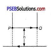
A long straight wire carrying current of 25 A rests on a table as shown in figure. Another wire PQ of length 1 m, mass 2.5 g carries the same current but in the opposite direction.
The wire PQ is free to slide up and down. To what height will PQ rise? (NCERT Exemplar)
Answer:
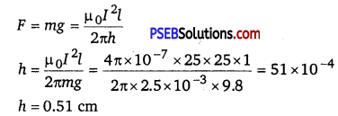
The magnetic field produced by long straight wire carrying current of 25 A rests on a table on small wire
B = \(\frac{\mu_{0} I}{2 \pi h}\)
The magnetic force on small conductor is , F = BIl sin θ = BIl
Force applied on PQ balance the weight of small current carrying wire.
Long answer type questions
Question 1.
Derive an expression for the force per unit length between two long straight parallel current carrying conductors. Hence define SI unit of current (ampere).
Answer:
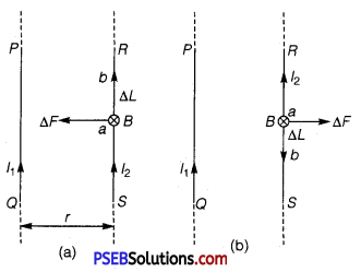
Suppose two long thin straight conductors (or wires) PQ and RS are placed parallel to each other in vacuum (or air) carrying currents I1 and Isub>2 respectively. It has been observed experimentally that when the currents in the wire are in the same direction, they experience an attractive force (fig. a) and when they carry currents in opposite directions, they experience a repulsive force (fig. b).
Let the conductors PQ and RS carry currents I1 and I2 in same direction and placed at separation r.
Consider a current-element ‘ab’ of length ΔL of wire RS. The magnetic field produced by current- carrying conductor PQ at the location of other wire RS.
B1 = \(\frac{\mu_{0} I_{1}}{2 \pi r}\) ………….(1)
According to Maxwell’s right hand rule or right hand palm rule number 1, the direction of B1 will be perpendicular to the plane of paper and directed downward. Due to this magnetic field, each element of other wire experiences a force. The direction of current element is perpendicular to the magnetic field; therefore the magnetic force on element ab of length ΔL
ΔF = B1I2ΔL sin90° = \(\frac{\mu_{0} I_{1}}{2 \pi r}\) I2 ΔL
∴ The total force on conductor of length L will be
F = \(\frac{\mu_{0} I_{1} I_{2}}{2 \pi r}\) ΔΣL = \(\frac{\mu_{0} I_{1} I_{2}}{2 \pi r}\)L
∴ Force acting per unit length of conductor
f = \(\frac{F}{L}\) = \(\frac{\mu_{0} I_{1} I_{2}}{2 \pi r}\) N/M …………… (2)
According to Fleming’s left hand rule, the direction of magnetic force will be towards PQ, i.e., the force will be attractive.
On the other hand if the currents I1 and I2 in wires are in opposite directions, the force will be repulsive. The magnitude of force in each case remains the same.
Definition of SI Unit of Current (Ampere) : In SI system of fundamental unit of current ‘ampere’ is defined assuming the force between the two current carrying wires as standard.
The force between two parallel current carrying conductors of separation r is
\(\frac{F}{L}\) = \(\frac{\mu_{0} I_{1} I_{2}}{2 \pi r}\) N/M
If I1 = I2 = 1A, r = lm, then
f = \(\frac{\mu_{0}}{2 \pi}\) = 2 x 10⁻⁷ N/m
Thus, 1 ampere is the current which when flowing in each of parallel conductors placed at separation 1 m in vacuum exert a force of 2 x 10⁻⁷ on 1 m length of either wire.
![]()
Question 2.
Draw the labelled diagram of a moving coil galvanometer. Prove that in a radial magnetic field, the deflection of the coil is directly proportional to the current flowing in the coil.
Or (a) Draw a labelled diagram of a moving coil galvanometer.
Describe briefly its principle and working.
(b) Answer the following:
(i) Why is it necessary to introduce a cylindrical soft iron core inside the coil of a galvanometer?
(ii) Increasing the current sensitivity of a galvanometer may not necessarily increase its voltage sensitivity. Explain, giving reason.
Or Explain, using a labelled diagram, the principle and working of a moving coil galvanometer. What is the function of (i) uniform radial magnetic field, (ii) soft iron core?
Or Define the terms (i) current sensitivity and (ii) voltage sensitivity of a galvanometer. Why does increasing the current sensitivity not necessarily increase voltage sensitivity?
Answer:
(a) Moving Coil Galvanometer: A galvanometer is used to detect current in a circuit.
Construction: It consists of a rectangular coil wound on a non-conducting metallic frame and is suspended by phosphor bronze strip between the pole-pieces (N and S) of a strong permanent magnet. A soft iron core in cylindrical form is placed between the coil.
One end of coil is attached to suspension wire which also serves as one terminal (Tx) of galvanometer. The other end of coil is connected to a loosely coiled strip, which serves as the other terminal (T2). The other end of the suspension is attached to a torsion head which can be rotated to set the coil in zero position. A mirror (M) is fixed on the phosphor bronze strip by means of which the deflection of the coil is measured by the lamp and scale arrangement. The levelling screws are also provided at the base of the instrument.
The pole pieces of the permanent magnet are cylindrical so that the magnetic field is radial at any position of the coil.
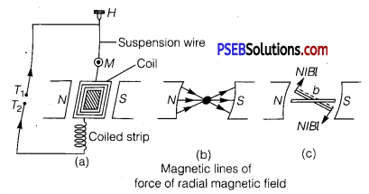
Principle and Working : When current (I) is passed in the coil, torque τ acts on the coil, given by
τ = NIABsinθ
where θ is the angle between the normal to plane of coil and the magnetic field of strength B, N is the number of turns in a coil.
When the magnetic field is radial, as in the case of cylindrical pole pieces and soft iron core, then in every position of coil the plane of the coil, is parallel to the magnetic field lines, so that θ = 90° and sin 90 ° = 1. The coil experiences a uniform coupler.
Deflecting torque, τ = NIAB
If C is the torsional rigidity of the wire and θ is the twist of suspension strip, then restoring torque = C0. For equilibrium, deflecting torque = restoring torque
i.e., NIAB = Cθ
θ = \(\frac{N A B}{C}\)I ………… (1)
i.e., θ ∝ I
Deflection of coil is directly proportional to current flowing in the coil and hence we can construct a linear scale.
Importance (or Function) of Uniform Radial Magnetic Field
Torque as current carrying coil in a magnetic field is τ = NIAB sinθ In radial magnetic field sinθ = 1, so torque is τ = NIAB.
This makes the deflection (θ) proportional to current. In other words, the radial magnetic field makes the scale linear.
(b)
(i) The cylindrical, soft iron core makes the (1) field radial and (2) increases the strength of the magnetic field, i.e., the magnitude of the torque.
(ii) Sensitivity of Galvanometer
Current sensitivity: It is defined as the deflection of coil per unit current flowing in it.
Sensitivity,
I = (\(\frac{\theta}{I}\)) = \(\frac{N A B}{C}\)………… (1)
Voltage sensitivity: It is defined as the deflection of coil per unit potential difference across its ends.
i.e., SV = \(\frac{\theta}{V}\) = \(\frac{N A B}{R_{g} \cdot C}\) …………. (2)
where Rg is resistance of galvanometer.
Clearly for greater sensitivity number of turns N, area A and magnetic field strength B should be large and torsional rigidity C of suspension should be small.
Dividing eqs. (2) by (1)
\(\frac{S_{V}}{S_{I}}=\frac{1}{G}\) = 1 ⇒ SV = \(\frac{1}{G}\) SI
Clearly, the voltage sensitivity depends on current sensitivity and the resistance of galvanometer. If we increase current sensitivity and resistance G is larger, then it is not certain that voltage sensitivity will be increased. Thus, the increase of current sensitivity does not imply the increase of voltage sensitivity.
