
Punjab State Board PSEB 12th Class Physics Important Questions Chapter 7 Alternating Current Important Questions and Answers.
PSEB 12th Class Physics Important Questions Chapter 7 Alternating Current
Very short answer type questions
Question 1.
Why is the use of AC voltage preferred over DC voltage? Give two reasons.
Answer:
The use of AC voltage is preferred over DC voltage because of
- the loss of energy in transmitting the AC voltage over long distance with the help of step-up transformers is negligible as compared to DC voltage.
- AC voltage can be stepped up and stepped down as per the requirement by using a transformer.
Question 2.
Explain why current flows through an ideal capacitor when it is connected to an AC source, but not when it is connected to a DC source in a steady state.
Answer:
For AC source, circuit is complete due to the presence of displacement current in the capacitor. For steady DC, there is no displacement current, therefore, circuit is not complete.
Mathematically, capacitive reactance
XC = \(\frac{1}{2 \pi f C}=\frac{1}{\omega C}\)
So, capacitor allows easy path for AC source.
For DC, / = 0, so XC = infinity.
So, capacitor blocks DC.
![]()
Question 3.
Define capacitor reactance. Write its SI units.
Answer:
Capacitor reactance is the resistance offered by a capacitor, when it is connected to an electric circuit. It is given by XC = \(\frac{1}{\omega C}\)
where, ω = angular frequency of the source
C = capacitance of the capacitor
The SI unit of capacitor reactance is ohm (Ω).
Question 4.
In a series LCR circuit, VL = VC ≠ VR What is the value of power factor for this circuit?
Answer:
Power factor = 1
Since VL = VC, the inductor and capacitor will nullify the effect of each other and it will be a resistive circuit.
For Φ =0; power factor cosΦ = 1
Question 5.
The power factor of an AC circuit is 0.5. What is the phase difference between voltage and current in this circuit?
Answer:
Power factor between voltage and current is given by cosΦ, where Φ is phase difference
cosΦ = 0.5 = \(\frac{1}{2}\) ⇒ Φ = cos-1 (\(\frac{1}{2}\)) = \(\frac{\pi}{3}\)
Question 6.
What is wattless current?
Answer:
When pure inductor and/or pure capacitor is connected to AC source, the current flows in the circuit, but with no power loss; the phase difference between voltage and current is \(\frac{\pi}{3}\) . Such a current is called the wattless current.
![]()
Question 7.
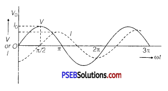
An AC source of voltage V = V0 sin ωt is connected to an ideal inductor. Draw graphs of voltage V and current I versus cat.
Answer:
Graphs of V and I versus ωt for this circuit is shown below:
Question 8.
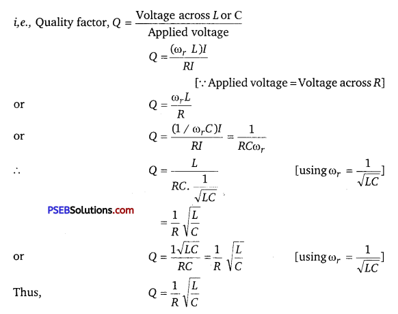
Define ‘quality factor’ of resonance in series LCR circuit. What is its SI unit?
Answer:
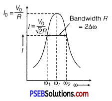
The quality factor (Q) of series LCR circuit is defined as the ratio of the resonant frequency to frequency band width of the resonant curve.
Q = \(\frac{\omega_{r}}{\omega_{2}-\omega_{1}}=\frac{\omega_{r} L}{R}\)
Clearly, smaller the value of R, larger is the quality factor and sharper the resonance. Thus, quality factor determines the nature of sharpness of resonance. It has no units.
Question 9.
What is the function of a step-up transformer?
Answer:
Step-up transformer converts low alternating voltage into high alternating voltage and high alternating current into low alternating current. The secondary coil of step-up transformer has greater number of turns than the primary (Ns > Np ).
![]()
Question 10.
Mention the two important properties of the material suitable for making core of a transformer.
Answer:
Two characteristic properties:
- Low hysteresis loss
- Low coercivity
Question 11.
If an LC circuit is considered analogous to a harmonically oscillating spring block system, which energy of the LC circuit would be analogous to potential energy and which one analogous to kinetic energy? (NCERTExemplar)
Answer:
Magnetic energy analogous to kinetic energy and electrical energy analogous to potential energy.
Question 12.
A device ‘X’ is connected to an a.c. source. The variation of voltage, current and power in one complete cycle is shown in the figure.
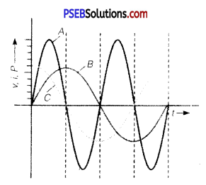
(a) Which curve shows power consumption over a full cycle?
(b) What is the average power consumption over a cycle?
(c) Identify the device ‘X’. (NCERT Exemplar)
Answer:
(a) A
(b) Zero
(c) L or C or LC
Short answer type questions
Question 1.
Prove that an ideal capacitor in an AC circuit does not dissipate power.
Answer:
Since, average power consumption in an AC circuit is given by
Pav = Vrms × Irms × cosΦ
But in pure capacitive circuit, phase difference between voltage and current is given by
Φ = \(\frac{\pi}{2}\)
∴ Pav = Vrms × Irms × cos \(\frac{\pi}{2}\)
⇒ Pav = 0 ( ∵ cos \(\frac{\pi}{2}\) = 0)
Thus, no power is consumed in pure capacitive AC circuit.
![]()
Question 2.
A circuit is set up by connecting inductance L 100 mil, resistor R -100 D. and a capacitor of reactance 200 Ω in series. An alternating emf of 150 √2 V, 500/ π Hz is applied across this series combination. Calculate the power dissipated in the resistor.
Answer:
Here, L =100 x 10-3 H,R =100 Ω,
XC = 200 Ω,Vrms = 150√2 V
v = \(\frac{500}{\pi}\) HZ
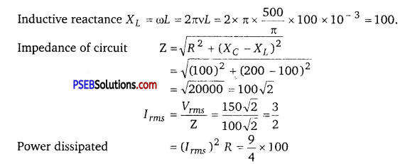
= 225 W
Question 3.
A series L-C-R circuit is connected to an AC source. Using the phasor diagram, derive the expression for the impedance of the circuit. Plot a graph to show the variation of current with frequency of the source, explaining the nature of its variation.
Answer:
Assuming XL > XC
⇒ VL > VC
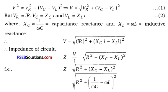
∵ Net voltage, V = \(\sqrt{V_{R}^{2}+\left(V_{L}-V_{C}\right)^{2}}\)
where, VL, VC and are alternating voltages across L,C and R respectively.
But, VR= IR,VL = IXL,
VC = IXC
∴ Net voltage, V = \(\sqrt{(I R)^{2}+\left(I X_{L}-I X_{C}\right)^{2}}\)
\(\frac{V}{I}\) = \(\sqrt{R^{2}+\left(X_{L}-X_{C}\right)^{2}}\)
Impedance of LCR circuit,
Z = \(\frac{V}{I}\) = \(\sqrt{R^{2}+\left(X_{L}-X_{C}\right)^{2}}\)
![]()
Question 4.
In a series LCR circuit connected to an AC source of variable frequency and voltage V = Vm sin ωt, draw a graph showing the variation of current (I) with angular frequency (ω) for two different values of resistance R1 and R2 (R1 > R2 ). Write the condition under which the phenomenon of resonance occurs. For which value of the resistance out of the two curves, a sharper resonance is produced? Define Q-factor of the circuit and give its significance.
Answer:
Figure shows the variation of im with ω in a LCR series circuit for two values of resistance R1 and R2 (R1 > R2).
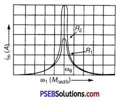
The condition for resonance in the LCR circuit is
ω0 = \(\frac{1}{\sqrt{L C}}\)
We see that the current amplitude is maximum at the resonant frequencyω. Since im = vm / R at resonance, the current amplitude for case R2 is sharper to that for case R1.
Quality factor or simply the Q-factor of a resonant LCR circuit is defined as the ratio of voltage drop across the capacitor (or inductor) to that of applied voltage.
It is given by Q = \(\frac{1}{R} \cdot \sqrt{\frac{L}{C}}\)
The Q-factor determines the sharpness of the resonance curve. Less sharp the resonance, less is the selectivity of the circuit while higher is the Q, sharper is the resonance curve and lesser will be the loss in energy of the circuit.
Question 5.
Both alternating current and direct current y, are measured in amperes. But how is the ampere defined for an alternating current? (NCERT Exemplar)
Answer:
An ac current changes direction with the source frequency and the attractive force would average to zero. Thus, the ac ampere must be defined in terms vc of some property that is independent of the direction of current. Joule’s heating effect is such property and hence it is used to define rms value of ac.
![]()
Question 6.
Explain why the reactance provided by a capacitor to an alternating current decreases with increasing frequency. (NCERT Exemplar)
Answer:
A capacitor does not allow flow of direct current through it as the resistance across the gap is infinite. When an alternating voltage is applied across the capacitor plates, the plates are alternately charged and discharged. The current through the capacitor is a result of this changing voltage (or charge). Thus, a capacitor will pass more current through it if the voltage is changing at a faster rate, i. e., if the frequency of supply is higher. This implies that the reactance offered by a capacitor is less with increasing frequency, it is given byl/©C.
Question 7.
Explain why the reactance offered by an inductor increases with increasing frequency of an alternating voltage.
(NCERT Exemplar)
Answer:
An inductor opposes flow of current through it by developing an induced emf according to Lenz’s law. The induced voltage has a polarity so as to maintain the current at its present value. If the current is decreasing, the polarity of the induced emf will be so as to increase the current and vice versa. Since the induced emf is proportional to the rate of change of current, it will provide greater reactance to the flow of current if the rate of change is faster, i.e., if the frequency is higher. The reactance of an inductor, therefore, is proportional to the frequency, being given by ωL.
Long answer type questions
Question 1.
(a) An AC source of voltage V = V0 sin ωt is connected to a series combination of L, C and R. Use the phasor diagram to obtain expression for impedance of the circuit and phase angle between voltage and current. Find the condition when current will be in phase with the voltage. What is the circuit in this condition called?
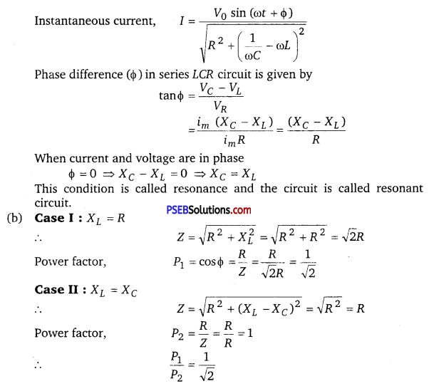
(b) In a series LR circuit XL = R and power factor of the circuit is P1. When capacitor with capacitance C such that XL = XC is put in series, the power factor becomes P2. Calculate \(\frac{P_{1}}{P_{2}}\).
Answer:
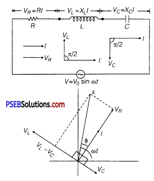
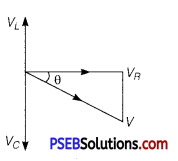
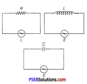
(a) Expression for Impedance in LCR Series Circuit : Suppose resistance R, inductance L and capacitance C are connected in series and an alternating source of voltage V = V0 sin ωt is applied across it. (fig. a) On account of being in series, the current (i) flowing through all of them is the same.
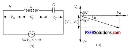
Suppose, the voltage across resistance R isVR, voltage across inductance L is VL and voltage across capacitance C is VC. The voltage VR and current i are in the same phase, the voltage VL will lead the current by angle 90° while the voltage VC will lag behind the current by angle 90° (fig. b). Clearly,VC and VL are in opposite directions, therefore their resultant potential difference = VC – VL (if VC >,VL).
Thus, VR and (VC – VL) are mutually perpendicular and the phase difference between them is 90°. As applied voltage across the circuit is V, the resultant of VR and (VC – VL) will also be V. From fig.
![]()
Question 2.
(i) What do you understand by sharpness of resonance in a series L-C-R circuit? Derive an expression for Q-factor of the circuit.
Three electrical circuits having AC sources of variable frequency are shown in the figures. Initially, the current flowing in each of these is same. If the frequency of the applied AC source is increased, how will the current flowing in these circuits be affected? Give the reason for your answer.
Answer:
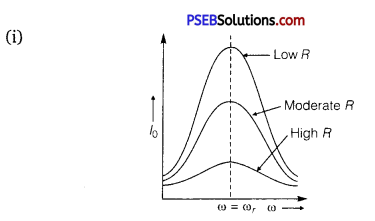
The sharpness of resonance in series LCR circuit refers how quick fall of alternating current in circuit takes place when frequency of alternating voltage shifts away from resonant frequency. It is measured by quality factor (Q-factor) of circuit.
The Q-factor of series resonant circuit is defined as the ratio of the voltage developed across the capacitance or inductance at resonance to the impressed voltage which is the voltage applied.
This is the required expression.
(ii) Let initially Ir current is flowing in all the three circuits. If frequency of applied AC source is increased, then the change in current will occur in the following manner.
(a) Circuit Containing Resistance R Only: There will not be any effect in the current on changing the frequency of AC source.
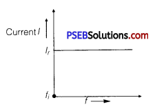
where,fi = initial frequency of AC source.
There is no effect on current with the increase in frequency.
(b) AC Circuit Containing Inductance
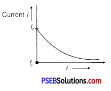
Only: With the increase of frequency current of AC source inductive reactance increase as
I = \(\frac{V_{r m s}}{X_{L}}=\frac{V_{r m s}}{2 \pi f L}\)
For given circuit,
I ∝ \(\frac{1}{f}\)
Current decreases with the increase of frequency.
(c) AC Circuit Containing Capacitor Only:
XC = \(\frac{1}{\omega C}=\frac{1}{2 \pi f C}\)
Current, I = \(\frac{V_{r m s}}{X_{C}}\) = \(\frac{V_{r m s}}{\left(\frac{1}{2 \pi f C}\right)}\)
I = 2πfCVrms
For given circuit, I ∝ f
Current increases with the increase of frequency.

![]()
Question 3.
(a) Describe briefly, with the help of a labelled diagram, the working of a step up transformer.
(b) Write any two sources of energy loss in a transformer.
(c) A step up transformer converts a low voltage into high voltage. Does it not violate the principle of conservation of energy? Explain
Or Draw a labelled diagram of a step-down transformer. State the principle of its working. Express the turn ratio in terms of voltages.
Find the ratio of primary and secondary currents in terms of turn ratio in an ideal transformer.
How much current is drawn by the primary of a transformer connected to 220 V supply when it delivers power to a 110 V-550 W refrigerator?
Answer:
(a) Transformer: Transformer is a device by which an alternating voltage may be decreased or increased. It is based on the principle of mutual-induction.
Construction: It consists of laminated core of soft iron, on which two coils of insulated copper wire are separately wound. These coils are kept insulated from each other and from the iron-core, but are coupled through mutual induction. The number of turns in these coils are different. Out of these coils one coil is called primary coil and other is called the secondary coil. The terminals of primary coils are connected to AC mains and the terminals of the secondary coil are connected to external circuit in which alternating current of desired voltage is required. Transformers are of two types:
1. Step-up transformer: It transforms the alternating low voltage to alternating high voltage and in this the number of turns in secondary coil is more than that in primary coil. (i. e.,Ns> Np).
2. Step-down transformer: It transforms the alternating high voltage to alternating low voltage and in this the number of turns in secondary coil is less than that in primary coil (i. e.Ns < Np)
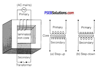
Working: When alternating current source is connected to the ends of primary coil, the current changes continuously in the primary coil; due to which the magnetic flux linked with the secondary coil changes continuously, therefore the alternating emf of same frequency is developed across the secondary.
Let Np be the number of turns in primary coil, Ns the number of turns in secondary coil and Φ the magnetic flux linked with each turn. We assume that there is no leakage of flux so that the flux linked with each turn of primary coil and secondary coil is the same. According to Faraday’s laws the emf induced in the primary coil
ε 0 = -Np\(\frac{\Delta \phi}{\Delta t}\) …………….. (1)
and emf induced in the secondary coil
ε s = -Np\(\frac{\Delta \phi}{\Delta t}\) ……………… (2)
From eq. (1) and eq, (2)
\(\frac{\varepsilon_{s}}{\varepsilon_{p}}=\frac{N_{s}}{N_{p}}\) …………………. (3)
If the resistance of primary coil is negligible, the emf (ε p) induced in the primary coil, will be equal to the applied potential difference (Vp) across its ends. Similarly if the secondary circuit is open, then the potential difference Vs across its ends will be equal to the emf (ε s) induced in it; therefore,
\(\frac{V_{s}}{V_{p}}=\frac{\varepsilon_{s}}{\varepsilon_{p}}=\frac{N_{s}}{N_{p}}\) r(say) …………… (4)
where r = \(\frac{N_{S}}{N_{P}}\) is called the transformation ratio. If ip and is are the instantaneous currents in primary and secondary coils and there is no loss of energy.
For about 100% efficiency,
Power in primary = Power in secondary
Vp ip = Vsis
∴ \(\frac{i_{s}}{i_{p}}=\frac{V_{p}^{F}}{V_{s}}=\frac{N_{p}}{N_{s}}=\frac{1}{r}\) ………….. (5)
In step-up transformer, Ns > Np → r > 1 ;
So Vs > Vp and is < ip
i.e., Step up transformer increases the voltage.
In step down transformer, Ns < Np → r < 1
So Vs < Vp and is > ip
i.e., step-up down transformer decreases the voltage, but increase the current.
Laminated Core: The core of a transformer is laminated to reduce the energy losses due to eddy currents. So, that its efficiency may remain nearly 100%.
In a transformer with 100% efficiency (say), Input power = output power dVpIp = VsIs
(b) The sources of energy loss in a transformer are, (i) eddy current losses due to iron core, (ii) flux leakage losses, (iii) copper losses due to heating up of copper wires, (iv) Hysteresis losses due to magnetisation and demagnetisation of core.
(c) When output voltage increases, the output current automatically decreases to keep the power same. Thus, there is no violation of conservation of energy in a step-up transformer.
We have, ip Vp = isVs = 550 W
Vp 220V
ip = \(\frac{550}{220}=\frac{5}{2}\) = 2.5A